Handwritten Digit Recognition App in C# tutorial
Project Files: Download
Hey guys,
Today we are going to build an app that can recognize hand written digits. It is a hard task to solve, because hand written digits are not perfect. In addition, they can have many different flavors depending on the person itself.
People tend to solve a problem like this using Neural Networks. Either fully connected or convolutional. However, there are many different approaches to solving this problem. And this is one of them.
Today we are building a solution that doesn’t use machine learning to solve this task. Therefore, we will use simple math and logic to classify the digits. After that, we will solve it with more advanced techniques and compare the results.
But, for right now, this is a perfectly good solution as introduction to this problem.
Handwritten Digit Recognition App in C#

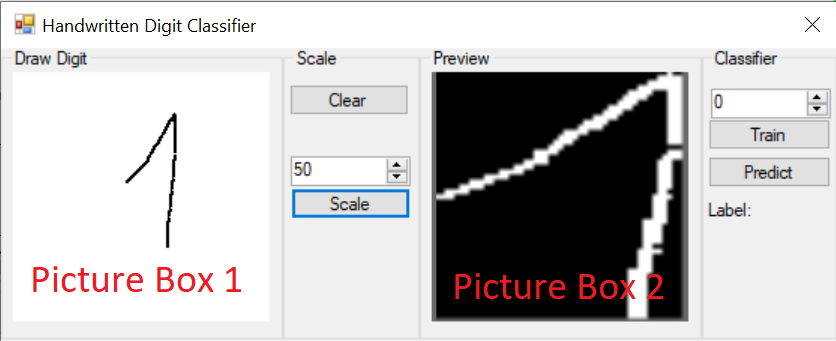
This is the application we are going to be building today.
It consists of two views. The first, allows the user to draw a letter. After that, the drawing is processed and displayed in the second view. Then the user can choose to Train or Predict an outcome.
Training adds the processed image in the data set.
Predict finds the most similar image to the drawn one.
The button clear allows the user to start a new drawing, while the button scale will start the image processing. On the other side of the app, the numeric up/down control allows the user to assign a label to the drawn image.
Accord .NET
We will be using Accord .NET library for the image processing. It is a .NET machine learning framework combined with audio and image processing libraries completely written in C#.
Handwritten Digit Recognition App in C# – Code Walkthrough

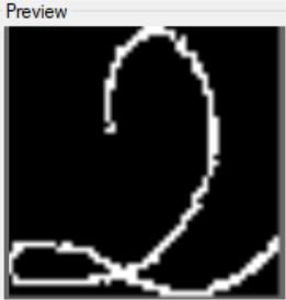
On the main form there are two picture boxes. The first one, allows the user to draw a number. The second, it displays the final processed image. Likewise, the _drawController is responsible for handling the drawing process by the user. It exposes the drawn result as a bitmap property called Drawing.
Because, raw pixel values don’t bring any value to this task, we need to process the image. As a result, we need to extract more descriptive features if we want to solve this task.
One way to extract good features from an image, is to use Convolution. But, this tutorial is not on convolution – at least not this one. So, let’s think simpler.
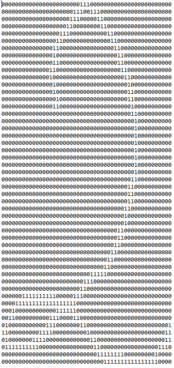
What if we extract the pixel values where the users pen has drawn to? This seems like a descriptive feature. But, instead of using the RGB pixel values, what if we created a so called Binarized Matrix. This matrix will contain only 1 and 0. Zero representing the area where the user has not drawn anything and 1 representing the opposite.

Now this is a better feature then just taking the raw pixel values. Let’s see how this binarized matrix will look like.

Because, our algorithm doesn’t work with matrices, we must flatten it. Matrix of rang mxn will produce a vector with mxn elements. In our case, because the scale is set to 50 it will produce vector with 2500 elements. All, either containing 0 or 1.
So what is the point of all of this? Why did we extract a feature like this?
Well the premise is, similar shapes will have similar distributions of elements. Meaning that the digit 2 will be more similar to another 2 then to the digit 1. So they will tend to cluster together. On the other side, 1’s will create their own cluster and so on.
The Image Processing

As you can see from the provided code, everything starts with the ImageProcessing class. It takes a Bitmap as input and then it goes through a series of transformations. First, it is Grayscaled. A grayscale image is one in which the value of each pixel is a single sample representing the amount of light; that is, it carries only intensity information. This is exactly what we were after. We wanted to lose the color information. Next, we simplify even more. We binarize the image.
A binary image is one that consists of pixels that can have one of exactly two colors, usually black and white. Not only does this help us with the classification of the drawn number, but also with detecting and cropping the drawn shapes.
Shape detection

Before we are able to locate the drawn shape, we must first, invert the image. As you can see inverting the image makes white pixels black, and black pixels white. We need this operation in order to use the BlobCounter class from Accord.NET. The BlobCounter class counts objects in image, which are separated by black background. It also provides their location, width and height as a Rectangle structure.
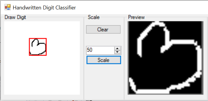
Crop whitespace from image
Another benefit to this process is that it allows us to loose the spatial information. In our case this is good. We don’t care where the digit is drawn in order to classify it. This way we decrease the number of additional variations to the input vector.
Image Resizing
Next step is to resize the image. All drawn digits in our case are resized into an image having 50px in width and height. Resizing the image allows us to decrease the amount of information we will need to process later on. It seems like image with size 50×50 is good enough. What I am trying to say is, this size displays enough details of the drawn image. If we were to say: use 10×10 we will loose information. With that we might loose pixels/lines that define the digit. So, we don’t want to size down the image too much. We need the digit lines clearly defined.
The Binary Matrix
The BinaryMatrix class accepts two arguments. The image and a float threshold. The binary matrix converts a grayscale or binary image into a binary matrix. Each pixel intensity is measured against the provided threshold. If the pixel intensity is bellow the value of 0.5 then the element is assigned the value of 0. Likewise, for a pixel value larger than 0.5 it assigns the value of 1.
The result matrix is shown bellow

Creating the Data Set
The algorithm we are going to use, in order to classify the digits does not accept a matrix form as input. It accepts a vector. This means that we have to convert the matrix to a vector. The process is called Flattening.

In order to create a DataPoint for our dataset, we must provide the input vector and the label. The input vector is a double array that is the result of the image matrix flattening. The Label is provided by the user.
The tuple of (vector,label) tells the DataSet which feature vector is assigned to which label. We will understand why we do this next.
Digit Classification
Finally, we will see how the classifier works

By now, we have created a DataSet consisting of feature vectors that uniquely describes the drawn digits, and labels assigned to those corresponding vectors. What we want to do next is take a new drawing by the user, and classify it.
Again, the newly drawn digit must go through the same processing up until this point. The only difference is that, this time we don’t add the vector to the DataSet. Instead, we make a prediction based on the calculated feature vector.
We make the prediction by comparing the distance between the newly computed feature vector, and the ones that are already in our DataSet. We find the smallest distance and assign that same class to our input vector.
This works well because of the premise we mentioned earlier. Similar input vectors tend to stay closer together.
Final Thoughts
Although this is an overly simple “Handwritten Digit Recognition” tutorial, it’s a good base for what we will do next. Next we will try to extract even more descriptive features out of the image. We will use convolution for that. Likewise, we will ditch this simple classification technique and substitute it with more advanced ML algorithm.
